MLX90640 Thermal Camera
Using an ESP-32 for Wi-Fi Connectivity
MLX90640
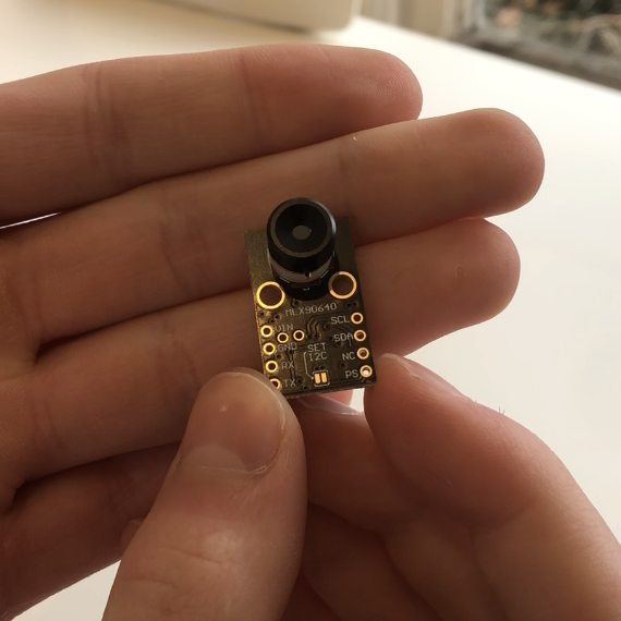
This is a 240*320 infrared array with an added wide angle lens that’s used for the project. The breakout board it resides on has both I2C and Serial communication protocols. The sensor also works with 3.3V logic making it perfectly compatible with an ESP-32.

Blynk-IOT
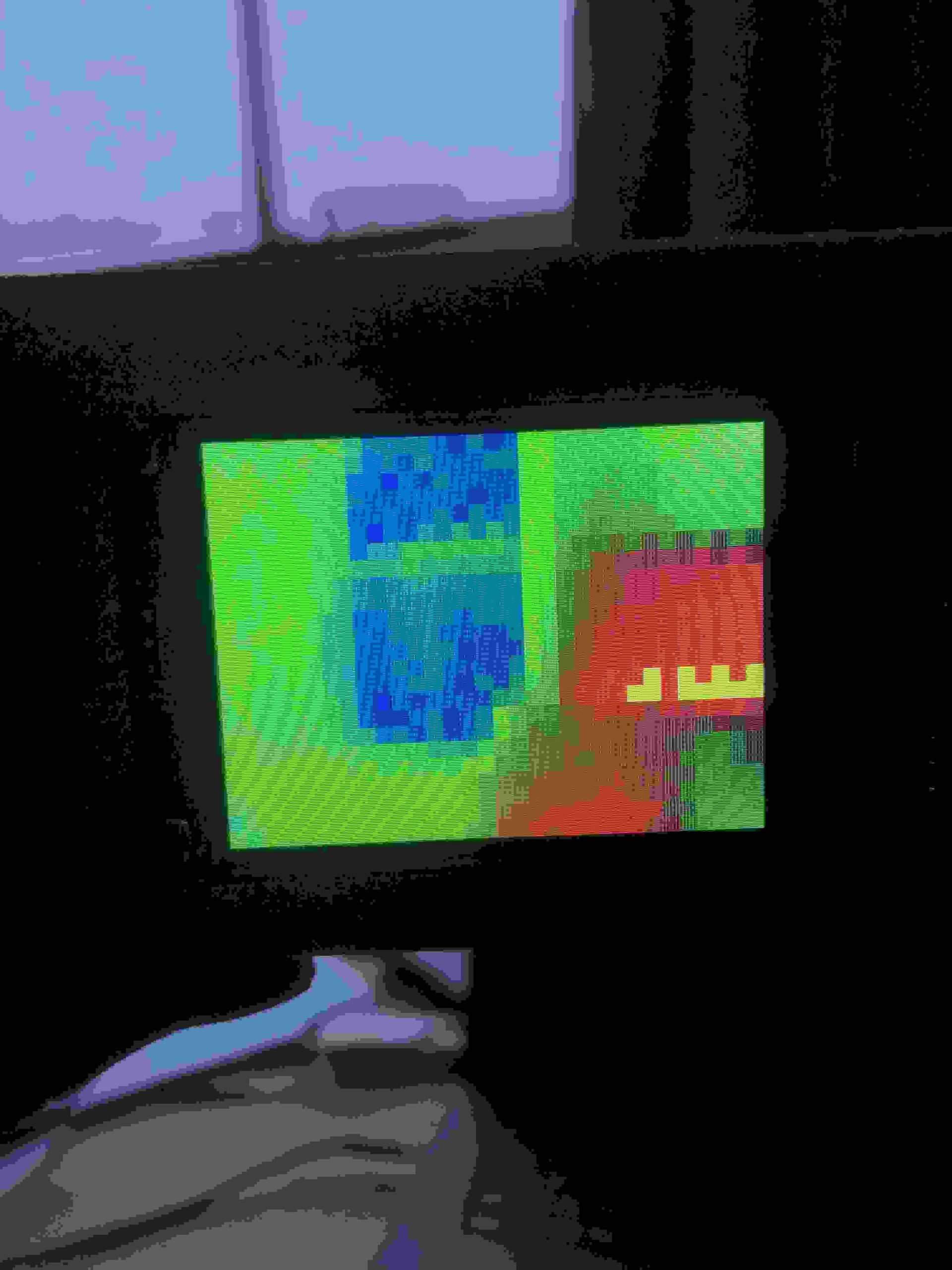
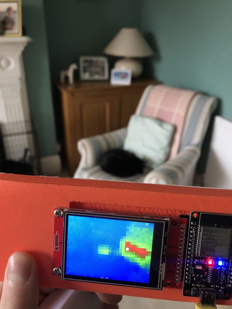
I wrote my own algorithm to convert the temperatures of each pixel into colours and it worked fairly well on the first try, but nothing beats trial and error.
Because I was making a lot of small changes to hardcoded values, I wasted a lot of time waiting for the sketch to upload. So I added a Wi-Fi control feature to the camera, allowing me to immediately change values without having to reupload.
Blynk-IOT WebApp
On the right you can see the web app I made using blynk’s prebuilt blocks meaning I can still avoid php for now! And yes, It was coded at 2am…..
When I physically built the camera, I hadn’t included any buttons which meant I wasn’t able to take still pictures. That’s why I added the “HOLD” function. Just like on a multimeter It holds the most recent frame like a picture.
The “COLOUR” switch is used to switch between algorithms used for colouring the data between the one I’ve coded, as seen in the pictures, to a more general purple-yellow one.
The final two inputs are parameters to my colourising algorithm, the average temp is the temperature which will appear a vibrant green on the display and the range is used to determine the maximum temperatures.
For example, an average temperature of 18 and a range of 10, would mean that the hottest temperature we wish to display would be 28. So 28 would be a bright red. Similarly 8 would be a deep blue and anything in-between would be part of the gradient. A smaller range means less precision, but more distinct colours – which can make an image easier to interpret.
