How It Works
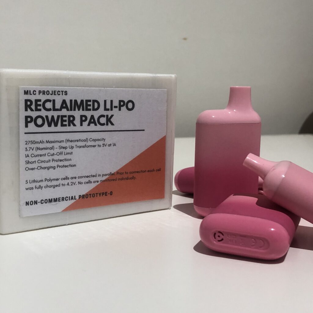
The smaller power pack is made from 5, 550mAh 3.7V Li-Po cells connected in parallel, whilst the bigger power pack is made from 12, 360mAh 3.7V Li-Po cells connected in parallel again.
Prior to connecting the cells together they were individually charged to their maximum 4.2V this is to prevent there being a large potential difference between the cells which would cause a surge of current to the least charged battery, possibly leading to thermal runaway of the batteries and a large fire.
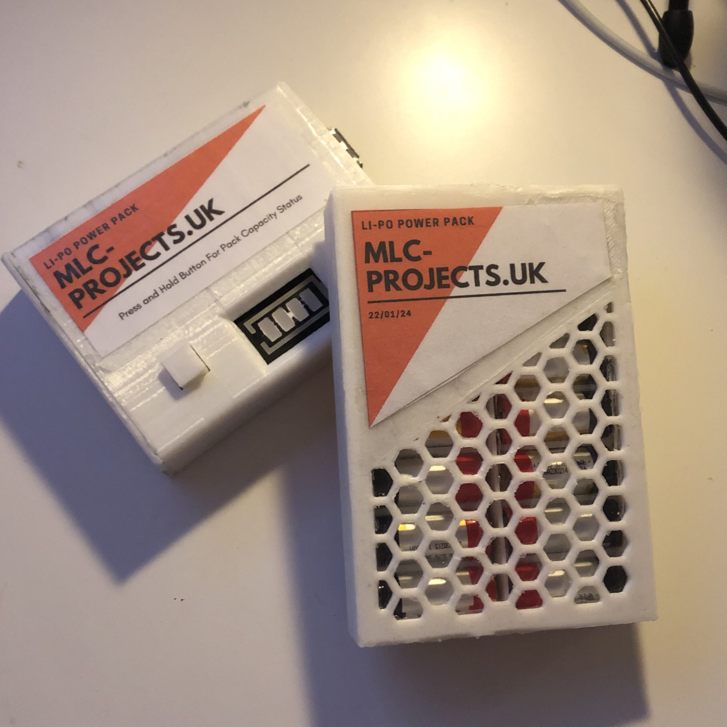
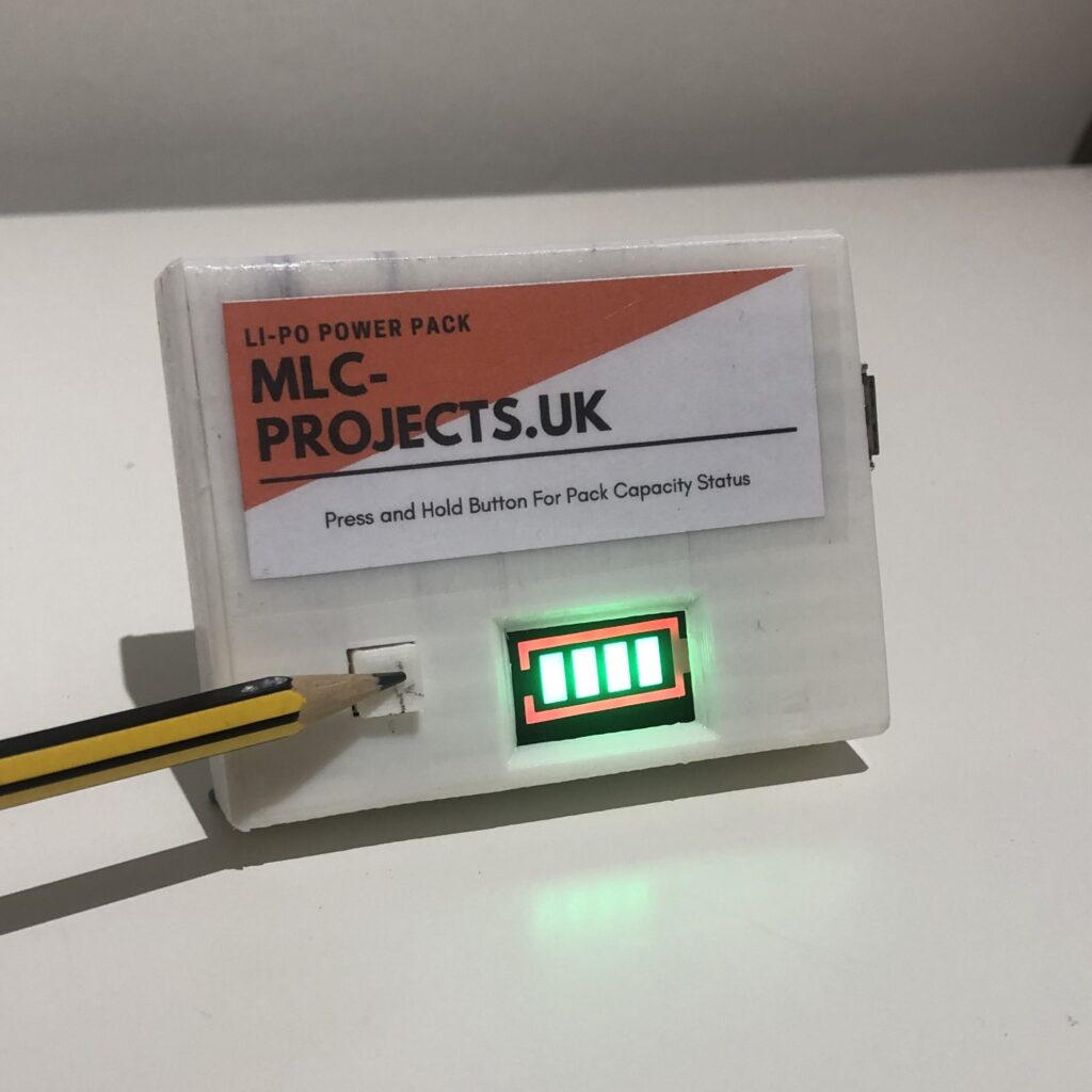
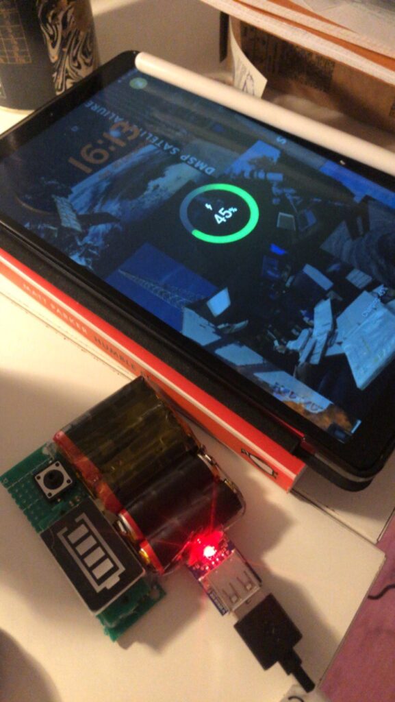
The 5 cells were reclaimed from dead disposable vapes which I found on the street. The power pack has a battery level indicator and a maximum capacity of 2750mAh which is enough to charge my phone once and a bit. The larger pack made from 12 cells has a maximum capacity of 4320mAh!
Read more about reclaiming Li-Po cells from vapes.
3.7 to 5 Volts
This is the step-up transformer I used to convert my smaller Li-Po pack into a usable phone charger, I noticed a few… inconveniences with the board however.
Firstly, to prevent discharging the batteries at a rate faster than they should be (1C), the board has a current cut off circuit at 1A. This means that if you use your phone whilst charging or you draw more current that 1A your device wont charge. Yippie!
Secondly, you can’t charge the cells whilst having an appliance plugged into the power pack, which ever process was happening first, is the one that’ll continue.
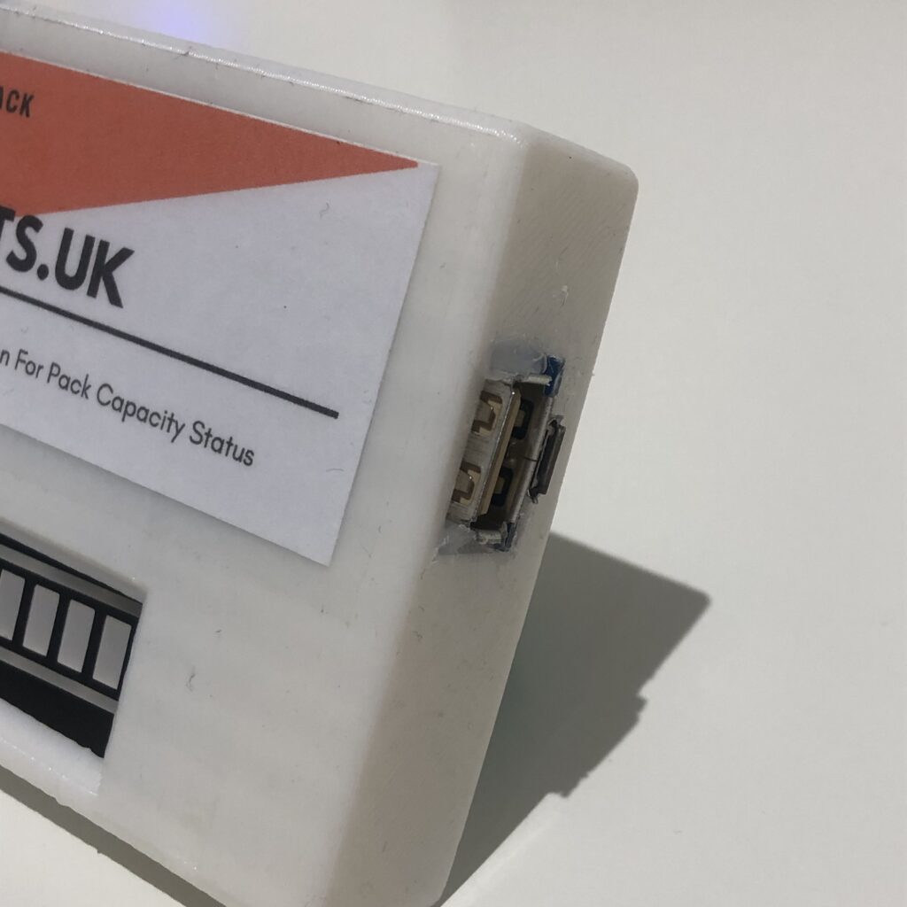
For my larger pack however I used this better 2A discharge board which uses USB-C and has a built in Battery Indicator.

Battery Indicator
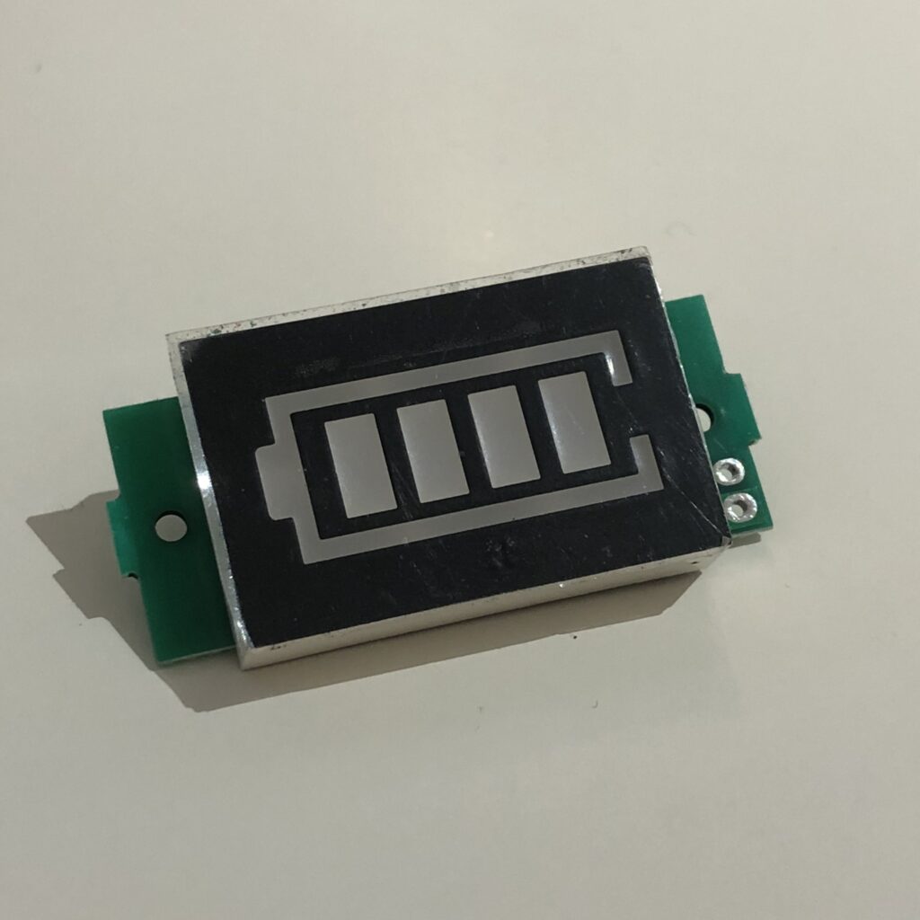
This is the indicator I used, it can be modified to work with cell voltages 3.7-29.6V (Nominal).
It uses a small microcontroller to turn on each rectangular segment at varying voltages (4 bars at 4.2V, 0 bars at 3.0V)
In my configuration of the circuit you have to press and hold a button which provides power to the module, however you have to wait a few seconds for the microprocessor to boot and display the relevant information.
